Totaline Thermostat Wiring Diagram
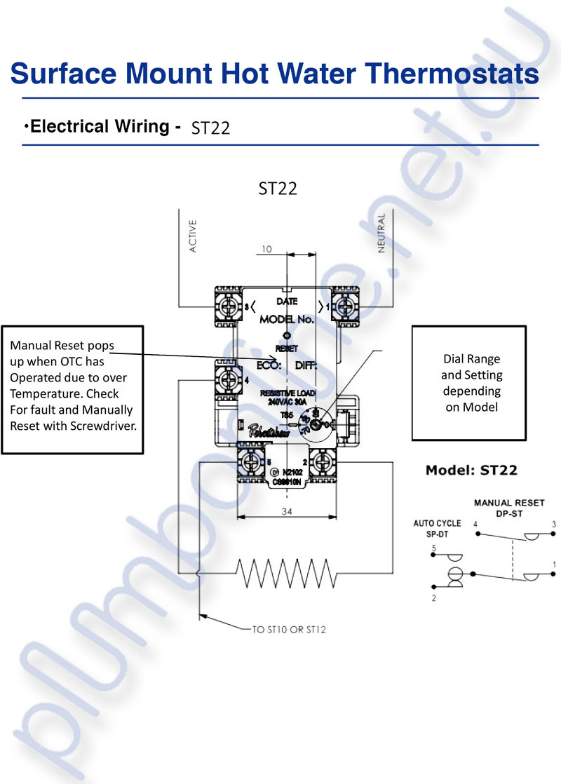
Tempstar Furnace Control Board Wiring Diagram, Tempstar ICP Gas Furnace Circuit Board Replaced, 38.06 MB, 27:43, 22,381, Anti DIY HVAC, 2020-09-10T01:38:43.000000Z, 19, Tempstar Tca030aka1 Wiring Diagram, wiringall.com, 800 x 600, jpeg, tempstar, 20, tempstar-furnace-control-board-wiring-diagram, Anime Arts
Residential heat pumps, split systems & package units, with no auxiliary heat. Fan power g r compressor y w y b o g r reversing valve o 4 conductor 18 to 22 gauge unshielded cable from the thermostat to the equipment. The wiring for the totaline unit is as follows: Here you can easily below is a typical wiring diagram for a totaline p thermostat.
Part numbers pc, pc, pc. Get totaline p374 wiring diagram keep in mind, it may take a few seconds for blower to energize relay and come on. the thermostat w. Totaline thermostat wiring diagram. Another way would be to simply. Indicates the thermostat is in the programming mode. Locked indication locked appears after the right combination of buttons are pressed, rendering the buttons inoperative. Start / stop indication start or stop appears when programming timer functions. Sample wiring diagrams 5 wire, 1 stage cooling, 2 stage heat, heat pump with o reversing valve. Residential heat pumps, split systems & package units, with auxiliary heat.
Totaline Thermostat P274 Wiring Diagram

Totaline Thermostat P274 Wiring Diagram
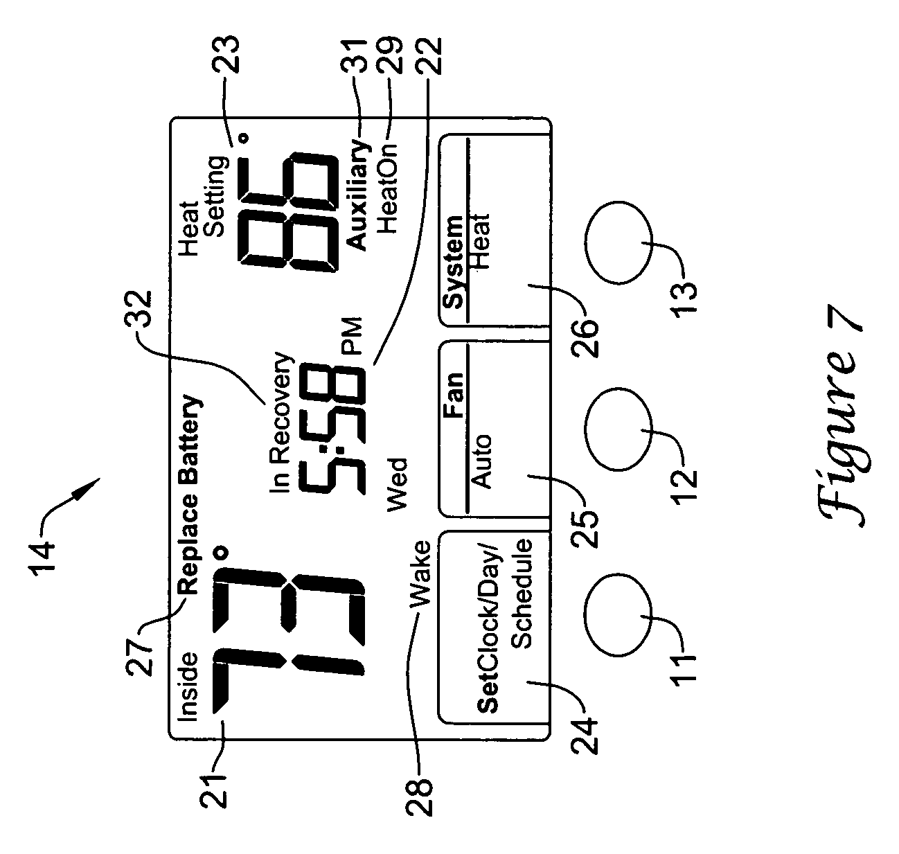
Totaline Thermostat P274 Wiring Diagram

Totaline Thermostat Wiring Diagram

Totaline Thermostat Wiring Diagram P474
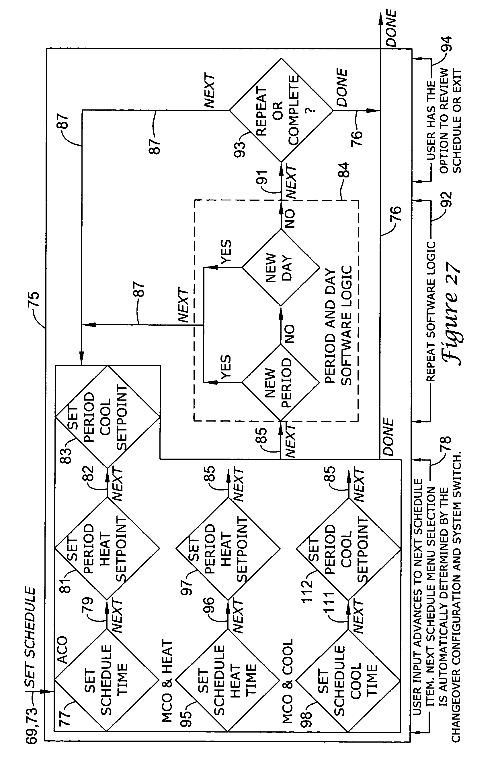
Totaline Thermostat Wiring Diagram P474 – Collection | Wiring Collection
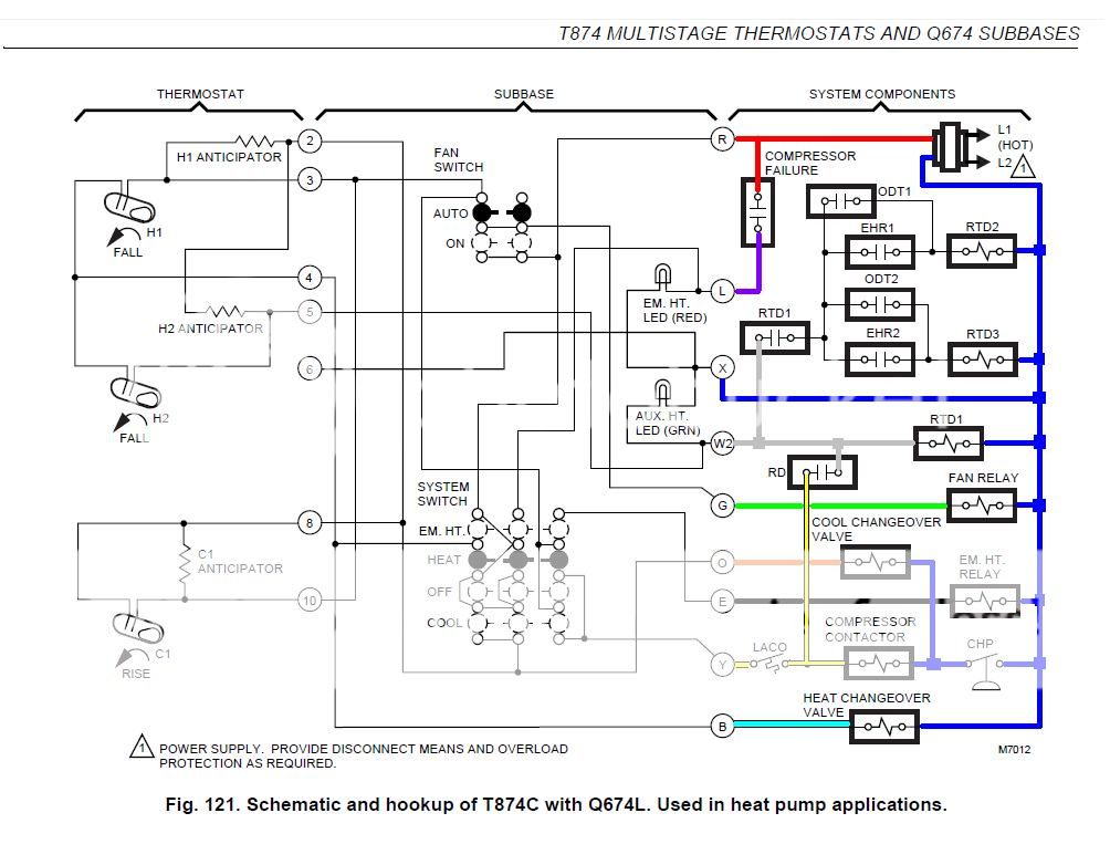
Totaline Thermostat Wiring Diagram

Totaline Thermostat P274 Wiring Diagram
Totaline Thermostat P274 Wiring Diagram

Totaline Thermostat Wiring Diagram - erinnanto
